
Is Code the Universal Representation? Part One
Inspired by “Coding Models之后” (After Coding Models) by Hokin的学术笔记 (Hokin’s Academic Notes) — original post. [1] An English translation of the original post is available (translated by GPT-6). All credit for the ideas under examination goes to the original author; any mistakes in my checking are mine.
I came across a thought-provoking post — “After Coding Models,” eleven images, dense with claims. The core observation is hard to argue with: today’s strongest coding models don’t just write software. They generate images, animations, 3D scenes, and interactive environments by writing executable programs. Then comes the big question: is code the optimal universal representation? Can you express anything — a photograph, a video, a world — as a program?
The question the post poses stuck with me: if code can express images, video, 3D scenes — is it the optimal universal representation? It’s a seductive idea. But there’s a gap between expressing something and understanding it: a program that renders a room doesn’t necessarily grasp the room the way a model trained on a million rooms might. I wanted to see how much of the claim survives contact with evidence. This is the first of a short series working through them one at a time — mostly to organize my own thinking, and in case it’s useful to others.
Claim 1: code can produce an image with no diffusion model
The first claim held up better than I expected. Here’s the idea, stripped down: a program describes a scene — where the objects are, what they’re made of, where the light is, where the camera sits. A renderer then computes how light bounces around that scene and what the camera sees. Reflections, refraction through glass, soft shadows — all of it falls out of the math. No diffusion model, no training data, no image assets anywhere in the loop. [2]
To make it concrete, I had a model write a small ray-tracer in Python and NumPy: three spheres on a checkerboard floor, a warm area light, a camera. Nothing else. It ran on CPU for about a minute and a half and produced this:
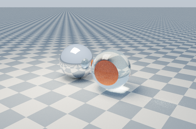 Rendered entirely from code: analytic spheres, procedural checkerboard, area light, path tracing. No diffusion model, no textures, no assets.
That’s a real image, computed from a scene description. The reflections and the glass refraction aren’t faked — they’re the renderer solving light transport from the geometry the program specified.
The honest caveats
I should be upfront about the limits here, because they matter. This image looks like simple CGI, not a photograph — you can see the sampling noise if you look closely. And notice where the intelligence actually lives in this pipeline: the renderer does the heavy lifting of turning geometry into pixels. The model’s job was to write down the scene: sphere positions, materials, light, camera. Describing a scene precisely in code is genuinely useful work, but it’s not the same as understanding what a room looks like from having seen a million rooms.
There’s a deeper point the experiment makes visible: the renderer can’t invent what the program doesn’t specify. It won’t recover the furniture of a real room from an incomplete description. Every detail in that image — the checkerboard, the cyan tint in the glass — came from the program or the renderer’s math. A learned image model, by contrast, fills in rich appearance from its training: textures, environments, grime on the floor. It just can’t tell you exactly where anything is.
So the first claim holds up, within its boundaries: code can express a scene and render it without any learned image model. Representability is established. But representability is the easy question. The hard ones — whether code is the efficient way for a model to learn spatial understanding, and whether it generalizes without shortcuts — need different evidence. To the original author’s credit, he retracted his own earlier warning on exactly this point, and I’ll take that up in a later installment.
Control vs. photorealism
The more revealing test, to me, was a head-to-head: the same scene description, given two ways. Once as a coding brief — write a program that renders this scene. Once as a plain image prompt — just generate the picture. Then two follow-up edits applied to each: turn the small sphere blue, and move the camera to the other side.
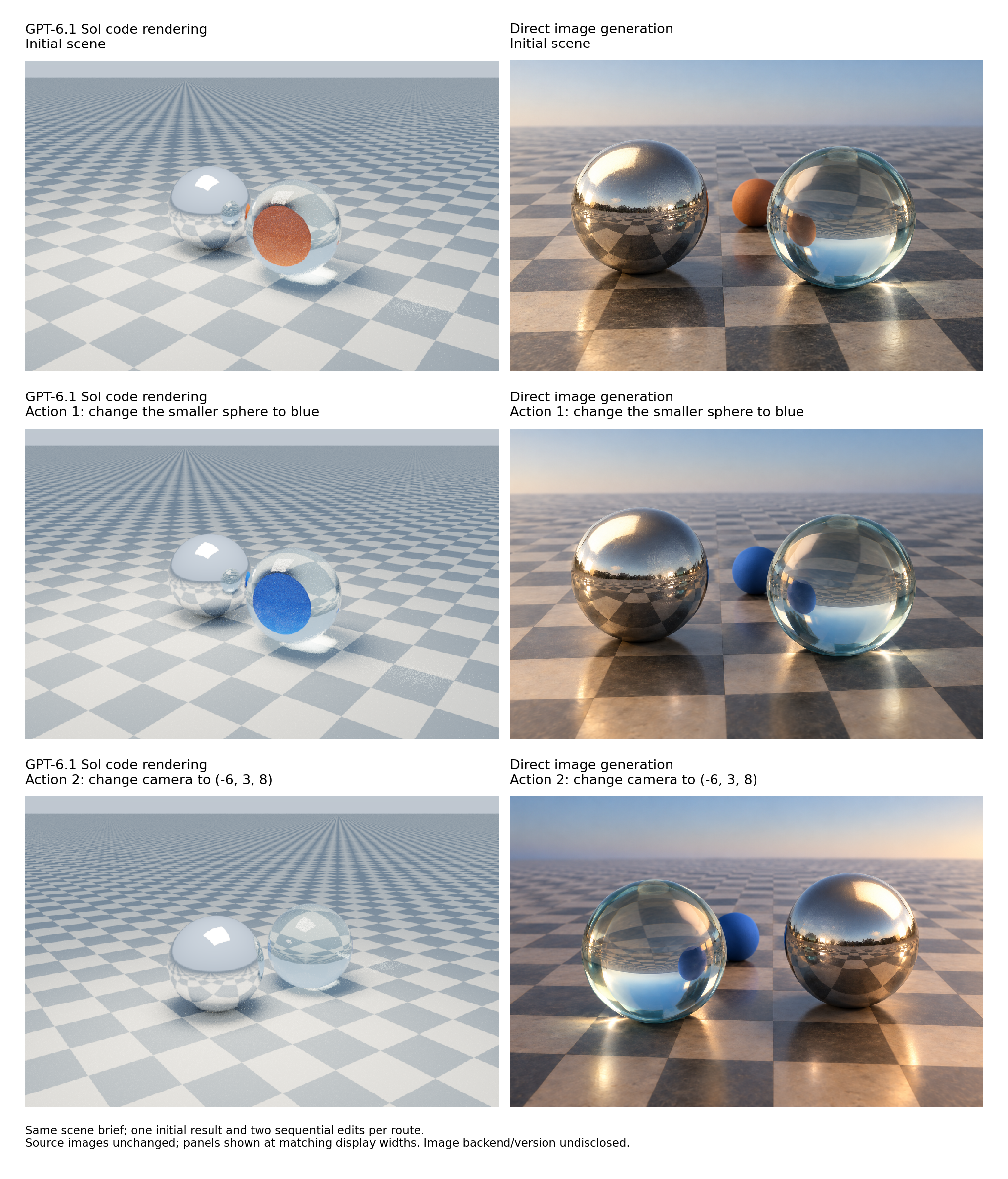 Same brief, two routes, two edits. The third row is the telling one: after the camera move, the code route keeps the chrome sphere on the left; the generated image flips the scene.
The base images tell one story: the generated one looks more photographic — textured floor tiles, an outdoor world reflected in the chrome — while the code output looks like simple CGI. The learned image model fills in rich appearance from its training; the program only knows what it was told.
The blue-sphere edit went fine on both sides. But the camera move is where it gets interesting. Moving the camera from one side to the other should keep the chrome sphere on the left and the glass on the right — I verified this by projecting the actual 3D coordinates through the new camera. The code route does exactly that: same world, new viewpoint, occlusion updates correctly. The generated image, meanwhile, produces a plausible-looking new picture with the spheres reversed — glass on the left, chrome on the right. It looks convincing. It’s just wrong.
That’s the tradeoff in one image: pretty is not the same as correct. Code gives you an inspectable scene — named parameters for every object, light, and camera angle that you can check and constrain. Direct generation gives you a beautiful picture with no guarantees about the world behind it. For anything where the geometry matters — and in the physical world, it always does — that inspectability is worth more than photorealism.
What’s next
Representability is established and control is real. But the harder questions remain: whether code is the efficient way for a model to learn spatial understanding, and whether it generalizes without shortcuts. The original author retracted his own earlier warning on exactly this point — next, I’ll work through what that retraction does and doesn’t settle.
This is part 1 of a series examining the claims in “After Coding Models.” Next: Encoding Isn’t Understanding? Part Two
Appendix: code, prompts, and data
Everything below is from the investigation this post is based on. The full source files live in this repo: rendering probe · comparison renderer · prompts · edit actions · render logs · image-tool logs · camera projection checks.
To rerun the rendering experiments (Python 3, NumPy installed):
python coding_render_probe.py
python coding_image_comparison.py --variant all
The code-generation brief (sent to the model; it wrote the renderer)
```text Write a self-contained Python program that produces the scene described below by calculating ray intersections and light transport. Use NumPy and the Python standard library only. Do not call any image-generation model or use downloaded assets, images, textures, meshes, external renderers or raster images. Represent the spheres analytically and compute the checkerboard procedurally. Implement diffuse indirect illumination, a rectangular area light, approximate rough-metal reflection, and glass reflection/refraction with Fresnel behavior and absorption. Save a 640 x 420 RGB PNG. Use 144 samples per pixel, at most 9 path bounces, and random seed 20261003. Print the measured rendering time. Produce the source code, not a drawing made by another image tool. SCENE Create a landscape image of a simple three-sphere scene on an infinite checkerboard floor, with no text or additional objects. Use a right-handed coordinate system with Y pointing up and distances in arbitrary scene units. The floor is at Y=-1. Its alternating warm-gray and cool-dark-gray squares have side length 1.1. Place a slightly rough chrome sphere of radius 1 at (-1.35, 0, 0); a clear solid glass sphere of radius 1 at (1.10, 0, 0.15), refractive index 1.5 and a faint cyan tint; and a smaller matte terracotta sphere of radius 0.52 at (0.15, -0.48, -2.0). All three rest on the floor. From the camera, the chrome sphere should appear on the left, the glass sphere on the right and closer, and the smaller terracotta sphere behind them, partly occluded and visible through refraction in the glass. Use a perspective camera at (6, 3, 8), aimed at (0, -0.03, -0.25), vertical field of view 37 degrees, aspect ratio 32:21. Light the scene with a large warm rectangular softbox at Y=6, spanning X=-3.5 to 0.5 and Z=-1 to 3, and a pale blue-gray sky. Show the bright softbox reflection, reflected checkerboard, refraction through the glass, soft contact shadows and indirect illumination. Aim for a convincing photograph of physical objects with coherent perspective and material behavior. ```The direct image-generation prompt (same scene, sent to the image tool)
```text Generate one image directly from the scene description below. Use only this text; do not use a reference image. Do not return code. Aim for a convincing photograph while preserving the specified object count, relative placement, materials, lighting and camera. Requested landscape aspect ratio: 32:21. No labels, text or watermark. SCENE Create a landscape image of a simple three-sphere scene on an infinite checkerboard floor, with no text or additional objects. Use a right-handed coordinate system with Y pointing up and distances in arbitrary scene units. The floor is at Y=-1. Its alternating warm-gray and cool-dark-gray squares have side length 1.1. Place a slightly rough chrome sphere of radius 1 at (-1.35, 0, 0); a clear solid glass sphere of radius 1 at (1.10, 0, 0.15), refractive index 1.5 and a faint cyan tint; and a smaller matte terracotta sphere of radius 0.52 at (0.15, -0.48, -2.0). All three rest on the floor. From the camera, the chrome sphere should appear on the left, the glass sphere on the right and closer, and the smaller terracotta sphere behind them, partly occluded and visible through refraction in the glass. Use a perspective camera at (6, 3, 8), aimed at (0, -0.03, -0.25), vertical field of view 37 degrees, aspect ratio 32:21. Light the scene with a large warm rectangular softbox at Y=6, spanning X=-3.5 to 0.5 and Z=-1 to 3, and a pale blue-gray sky. Show the bright softbox reflection, reflected checkerboard, refraction through the glass, soft contact shadows and indirect illumination. Aim for a convincing photograph of physical objects with coherent perspective and material behavior. ```Edit 1 — recolor the small sphere
```text Change only the smaller matte terracotta sphere to saturated matte blue. Keep the chrome and glass spheres, their positions and sizes, the checkerboard, camera, crop and lighting unchanged. Update reflections and refraction where this material change physically affects them. Add no objects. ``` In the program this changed the small sphere's diffuse albedo from `[0.56, 0.13, 0.055]` to `[0.035, 0.15, 0.65]`; everything else stayed fixed and the renderer recomputed the image.Edit 2 — move the camera, keep the world fixed
```text Starting from the blue-sphere scene, move the perspective camera from (6, 3, 8) to (-6, 3, 8). Keep its target (0, -0.03, -0.25), vertical field of view 37 degrees and aspect ratio 32:21. Keep all sphere centers, radii, materials, the floor and light fixed in world coordinates. Render the new viewpoint with the resulting changes in overlap, visibility, reflections and refraction. Do not mirror the old image or redesign the scene. No additional objects or text. ``` Projecting the sphere centers through the new camera puts chrome at 40.4% and glass at 60.1% of image width from the left — chrome stays left of glass. The code output matches; the generated image reverses them.References
[1] Hokin的学术笔记. (n.d.). Coding Models之后 [After Coding Models]. Eleven-image Chinese illustrated post. Original post. English translation (translated by GPT-6).
[2] Pharr, M., Jakob, W., & Humphreys, G. (2023). Physically Based Rendering: From Theory to Implementation (4th ed.). Open textbook.
Comments